Plan Memory
This document describes the PlanMemory transformation (PlanMemoryPass) in HIVM: hardware context, algorithm, API, and constraints.
Hardware Background
Ascend on-chip memory uses a buffer model. It includes storage for the Cube (matrix) and Vector units. Software must control addresses explicitly and respect alignment.
For Atlas A2 training/inference products, the hardware architecture [1] is as follows.
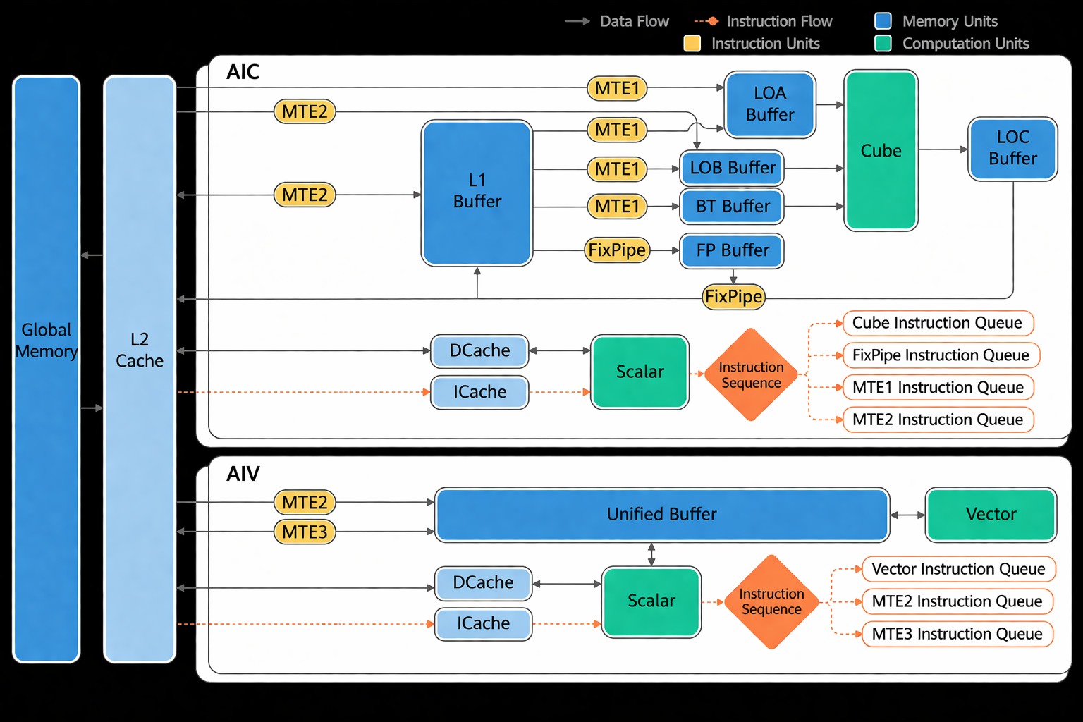
Buffer alignment requirements
Buffer |
Alignment |
Role |
|---|---|---|
Unified Buffer (UB) |
32 bytes |
General cache for vector/scalar ops |
L1 Buffer |
32 bytes |
Temporary feature maps and other convolution data |
L0A Buffer |
512 bytes |
Temporary left matrix (e.g. feature map) for matrix ops |
L0B Buffer |
512 bytes |
Temporary right matrix (e.g. weight) for matrix ops |
L0C Buffer |
512 bytes |
Temporary matrix op intermediate and output |
BT Buffer |
64 bytes |
BiasTable for matrix bias |
FP Buffer |
64 bytes |
Fixpipe: quantization/ReLU parameters, etc. |
Algorithm Principle
Software Background
In the input IR, memref.alloc buffers have a name and size but no address. The AscendNPU IR memory module (PlanMemory) assigns addresses based on lifetime to avoid overwrites and precision issues. To fit all buffers in limited on-chip memory, PlanMemory performs memory reuse using IR semantics and hardware rules. To avoid unnecessary data dependencies that hurt performance, it uses a three-level allocation strategy to balance performance and utilization.
On-chip memory allocation targets storage units (including UB, L1, and L0C) involved in Cube (matrix) and Vector compute units. Cube uses L0A/L0B for left/right matrices (loaded from L1) and L0C for matrix multiplication results and intermediate results; allocation is mainly for L1 and L0C. Vector accesses the UB, which stores the input and output of vector computation. Memory allocation also involves allocating memory for different buffers in the UB.
PlanMemory also allocates a small amount of Workspace (memref_ext.alloc_workspace) for CV flows. If Vector computation is required after Cube computation, Cube computation results need to be moved out of L0C, temporarily stored in Workspace, and then into the UB. Workspace size is reported to the framework runtime.
Terms
BufferLife: The lifetime of a buffer — from first write (gen) to last read (kill). Non-overlapping lifetimes can share the same memory; PlanMemory computes offsets so non-overlapping buffers reuse space.
Alias: Two values that refer to the same underlying data (e.g. before/after
subview).Inplace reuse: An op’s output can overwrite an input buffer (e.g. vcast f16→i16 same width). PlanMemory assigns the same offset to such output under hardware inplace rules.
Address offset / pointer_cast: After allocation, instead of a separate alloc, PlanMemory emits
hivm.hir.pointer_cast(offset)(byte offset in that memory space).
Implementation Principle
Source file: bishengir/lib/Dialect/HIVM/Transforms/PlanMemory.cpp
Main process:
Lifetime analysis: For each buffer in the IR, compute gen and kill.
Memory allocation: Allocate memory addresses from lifetime and reuse rules.
OP rewrite: Replace the original
allocwithhivm.hir.pointer_cast(offset), and write the start address back to the corresponding buffer for indication.
Lifetime analysis
Main process:
Use community
Livenessfor liveness analysis.Walk the IR (including
scf.for,scf.if,scf.while), collect gen (buffers defined) and kill (buffers last use) per op to get BufferLife.Compute lifetime per buffer (first write to last read). Non-overlapping lifetimes may share memory.
Use Alias to identify inplace candidates and assign the same base address where valid.
Memory allocation
There are two memory allocation modes: sequential and reuse. If the sum of buffer sizes fits in a Memory Scope (e.g. UB, L1), sequential allocation is used. Otherwise, reuse is applied, ensuring that reuse does not cause conflicts.
Reuse allocation includes inplace and three-level reuse.
Inplace
Conditions:
The Memory Scope is the same, for example, UB.
In an
A = B + Cpattern, A’s kill is C’s gen.Hardware constraints are met.
Three-level reuse
The compiler tries higher levels first and rolls back to a lower level if allocation fails.
[1] Level2
Different pipelines (PIPE) run in parallel. Reusing memory across pipelines can add dependencies and hurt throughput.
Level2: Prefer reuse within the same pipeline type (e.g. Vector with Vector), so non-DMA pipelines reuse first.
Example:
Shared A [A0, A1]
Shared B [B]
Shared C [C]
Shared D [D0, D1]
Loop i:
  // sync
  op1(A0, A1) // DMA OP, Double Buffer
  op2(B)      // Vector OP
  op3(C)      // Vector OP
  op4(D0, D1) // DMA OP, Double Buffer
With double buffering, A and D use two buffers each for DMA. When shared memory is tight, reusing C with A would introduce an extra dependency between op1 (DMA PIPE) and op4 (Vector PIPE), so MTE_PIPE and V_PIPE could not run in parallel and performance would drop.
With Level2, C reuses B; both are Vector ops, so V_PIPE is serial anyway and reuse does not add cross-pipeline dependency.
The following figure shows the pipeline effect before and after Level2 is used.
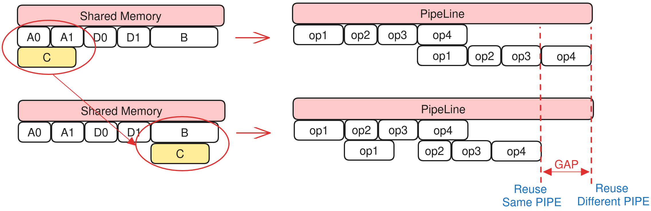
Pros: Same-pipeline reuse does not add cross-pipeline dependency; better overall performance.
Cons: Smaller reuse space; reuse may fail more often.
[2] Level1
Double buffering improves overlap of load and compute and is important for performance. If a single buffer reuses one slot of a double buffer, the double buffer cannot run in parallel and the pipeline stalls.
Level1: In the same loop, if a single buffer would reuse a double buffer, the single buffer is upgraded to a double buffer so both slots can be used without stalling.
Example:
Shared A [A0, A1]
Shared B [B]
Shared C [C]
Shared D [D0, D1]
Loop i:
  // sync
  op1(A0, A1) // DMA OP, Double Buffer
  op2(B)      // Vector OP
  op3(C)      // Vector OP
  op4(D0, D1) // DMA OP, Double Buffer
With double buffering, A and D use two buffers each for DMA. When shared memory is tight, if C (single buffer) reuses one slot of A, then op1 needs A0 while op3 still holds C (same as A0), so op1 must wait for op3 and the pipeline stalls.
With Level1, C is upgraded to a double buffer; op1 uses A0 while op3 uses C1 (backed by A1), so op1 does not wait for op3 and the pipeline can overlap.
The following figure shows the pipeline effect before and after Level1 is used.
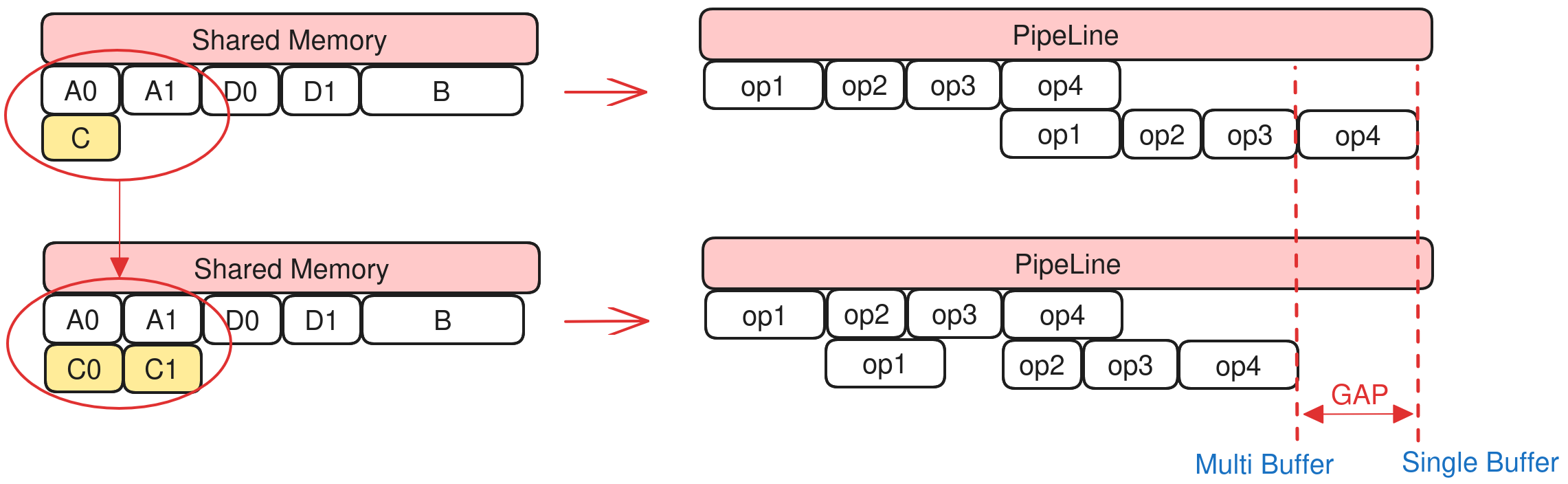
Pros: Avoids pipeline stall in double-buffer scenarios.
Cons: Extra buffer is required for the new double buffer; reuse success rate may be reduced.
[3] level0
Level0: Any two buffers with non-overlapping lifetimes can share memory.
The following figure shows the memory usage before and after Level0 is used.
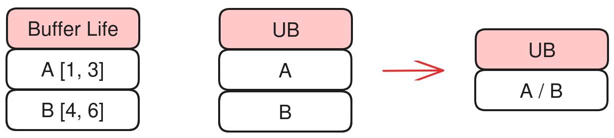
Pros: Achieves maximum reuse.
Cons: Ignores pipeline structure; bad reuse can hurt performance.
OP rewrite
After computing offsets, replace memref_ext.alloc_workspace (GLOBAL_WORKSPACE_PLAN) and memref.alloc (LOCAL_MEM_PLAN) with hivm.hir.pointer_cast(offset).
Tests
File: bishengir/test/Dialect/HIVM/plan-memory.mlir
Typical CHECK:
// CHECK-NOT: memref.alloc()
// CHECK: %[[CONST0:.*]] = arith.constant 0 : i64
// CHECK: {{.*}} = hivm.hir.pointer_cast(%[[CONST0]])
API
Option |
Default Value |
Description |
|---|---|---|
|
false |
Use |
|
false |
Reuse buffers in the workspace. |
|
false |
Restrict inplace to match ISA behavior. |
Constraints
The total size of buffers live at any one time must not exceed the actual hardware memory size for that scope.
[Note] The actual space occupied by each buffer is automatically byte-aligned. For the alignment size, see [Hardware Background](#Hardware Background).
Otherwise, PlanMemory fails with a scope overflow error, such as UB overflow.
loc("/tmp/tmp0h121237/kernel.ttadapter.mlir":2:3): error: ub overflow,
requires 3219456 bits while 1572864 bits available! (possible reason:
tiling basic block is too large or block number is more than what user
expect due to multi-buffer feature is enabled and some ops need extra local buffer.)